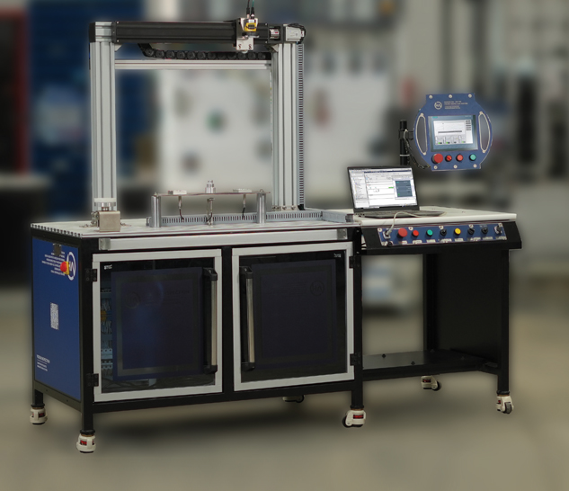
Vision Inspection Station With
PLC - HMI And Smart Vision System
Hytech Didactic Vision Inspection Station is a Mechatronics based training system designed to provide training on PLC HMI integrated Vision Inspection System. This station is equipped with Smart Vision system mounted on a single axis robot which can travel at least 500mm in linear axis making the total focal envelope of the vision system of at least 900 x 200mm.
User is expected to carry out vision inspection of test jobs by programming PLC, HMI, Servo Motor based liner slide and smart vision system. Vision Inspection Station is an individual station which can be integrated with Hytech Computer Integrated Manufacturing System. When integrated with Computer Integrated Manufacturing system, test jobs are loaded in the Vision Inspection Station by gantry mounted robot whereas in an individual system, these test jobs are loaded manually.
User can change the process as well as the PLC ladder and HMI screens depending on training requirements. This station is designed to provide students with real time industrial automation process and integration of various automation components such as PLC, HMI, Servo motors, Smart Vision Inspection System etc

Technical Details of Vision Inspection Station:
| Structure | |
|---|---|
| Total Dimensions | 2000mm x 720mm x 1670mm (HT) |
| Approximate Weight | 150 KG |
| Worksurface | Made in aluminum extrusions with minimum dimensions of 1000mm x 720mm |
| Operation Surface | Made in MDF of minimum 25mm thickness with minimum dimensions of 800mm x 720mm |
| Mobility | 4 Qty castor wheels with brakes |
| Servo Slides | |
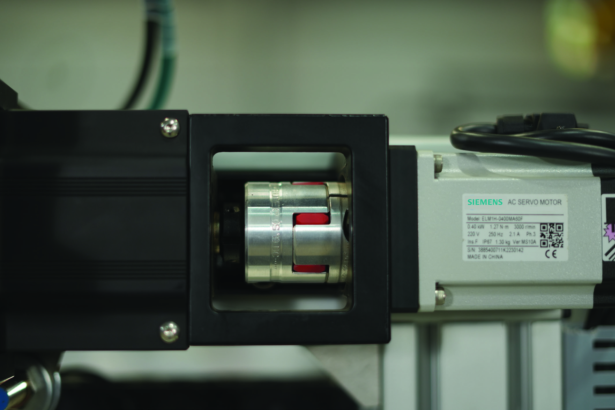
| Servo Slide 1 | Servo Slide with ball screw and LM Block |
| Minimum stroke of 500mm | |
| Servo Motor (AC Digital Servo) with minimum capacity of 400 Watt | |
| Servo Motor amplifier with PT Logic | |
| Drag Chain for Servo Slide 1 | |
| Aluminium profile based structure for servo slide mounting | |
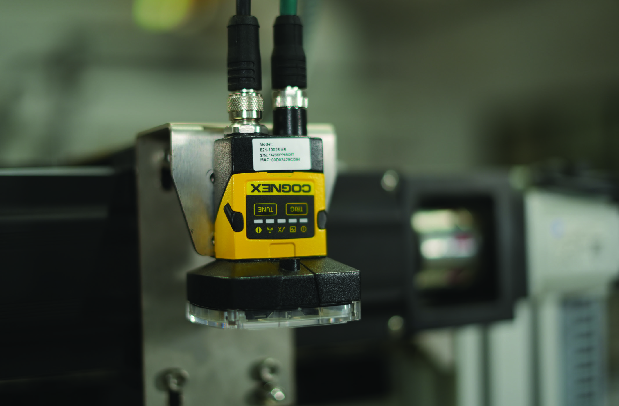
| Vision System | |
| Vision Camera | Cognex Vision System |
| Communication | Profinet |
| Vision Type | 2D Vision System |
| Software | Perpetual software for vision camera teaching and integration |
| Controller | |
| PLC | Siemens S7 1200 |
| HMI | Siemens KTP 700 HMI (Basic) |
| Switch | 5 Port unmanaged switch |
| I/O Link Infrastructure | |
| Master | i/o link based master with minimum 8 ports - M12 |
| Hub | i/o link based hub with minimum 8 ports - M12 (Suitable for 16 inputs / outputs) |
| Smart Light | i/o link based smart light with minimum 7 colours |
| Vision Pallet | |
| No of Cells | 4 |
| Sensors | Inductive Sensor for each cell |
| Rotary Vane motor | Rotary vane motor with minimum bore of 25 mm and FCV |
| Auto Feeder Station Bearing Auto Feeder | Pneumatic Guided Cylinder |
| Inductive Proximity sensor to sense metallic objects | |
| Pneumatic Gripper | Parallel gripper with minimum stroke of 10mm for each finger |
| Workstation | |
| CPU | Cognex Vision System |
| Operating System | Profinet |
| Monitor 1 | 2D Vision System |
| Monitor mounting stand | Dual monitor mounting stand |
| Software | |
| PLC | Siemens TIA Basic - Perpetual |
Vision Inspection Station Experiments:
Vision Inspection Station can be used individually as well as in integration with the entire CIM Setup. Vision Inspection Station is equipped with PLC as well as HMI and relevant software necessary for the PLC and HMI programming.
Even in integration setup with CIM, Vision Inspection Station will initiate the process once it receives the signal from Central Control Unit. It will complete entire task of Vision Inspection and pass on the signal of process completion to CCU (Master PLC) for further process.
For experimentation, user is expected to carry out all process cycles or experiments on Vision Inspection station in individual mode. In ideal scenario, Vision Inspection station is programmed individually and then integrated with the CIM setup.
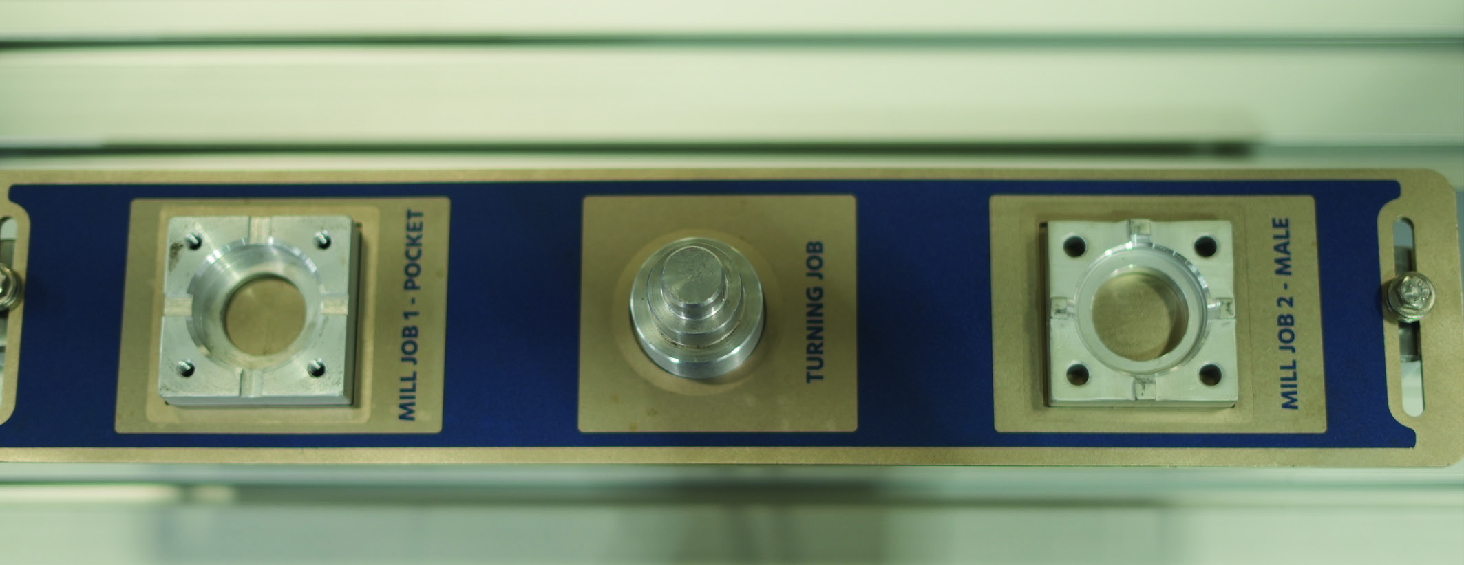
There are 3 jobs which are to be inspected in Vision Inspection Station before they are assembled together.
1. Mill Job 1 – Pocket Job
2. Mill Job 2 – Male Job
3. Turning job – Shaft